System Identification
Open-loop system identification derives a mathematical model of an electromechanical system by analyzing its frequency response. This model is subsequently utilized in the auto-tuning procedure.
Prerequisites
Prior to initiating the system identification procedure, verify the following conditions:
-
The motor is correctly connected and operational.
-
The mechanical system is securely fixed.
-
The motor shaft can rotate freely.
-
The torque control loop is fully functional and the commutation offset detection procedure has been performed.
-
Position and velocity feedback signals are present and provide valid data.
-
Applying a constant positive torque should result in positive velocity and an increasing position. Conversely, a negative torque should result in negative velocity and a decreasing position.
Note: The use of a Breaking Chopper Board is recommended to mitigate the risk of hardware damage.
Limitations
-
The procedure should be used carefully if the system has strict mechanical constraints.
-
For highly non-linear systems, the identified linear model may not accurately represent the actual system behavior.
-
The procedure cannot be performed if the mechanical system is sensitive to excessive vibration.
-
An accurate frequency response of the system is attainable only for frequencies up to 100 Hz due to communication constraints.
-
In systems with very high static friction, a small amplitude torque signal may lead to an overestimation of viscous friction and inertia.
-
The current implementation does not support limited range or hanging load system identification.
Usage
-
For many common applications, the default settings are suitable.
To begin, press “RUN SYSTEM IDENTIFICATION”. -
Note that the applied amplitude of the torque test signal changes linearly from 50% to 100% of the requested value.
-
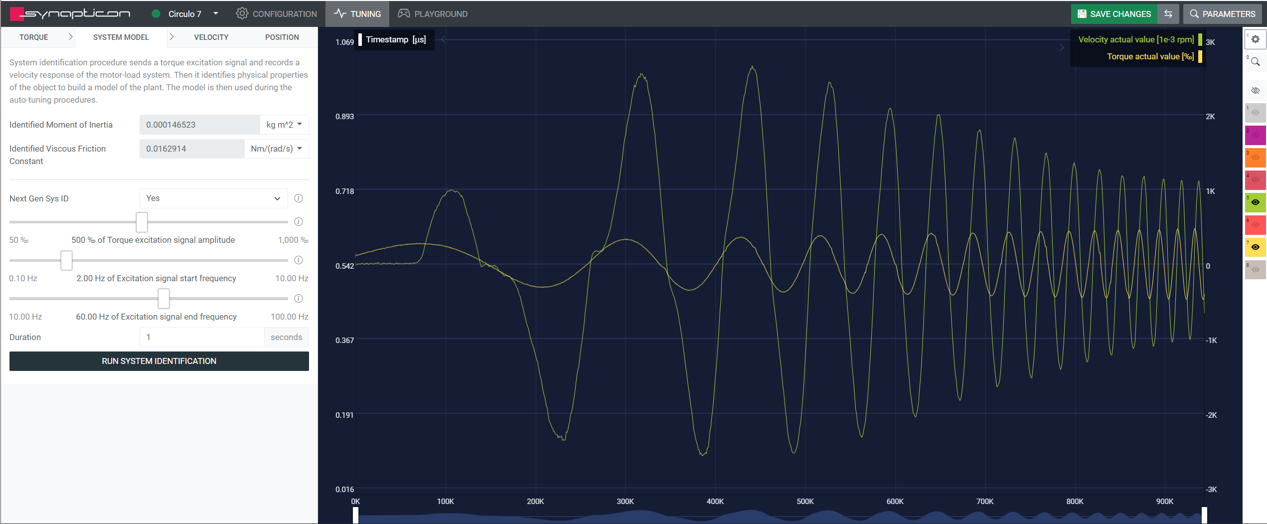
During the experiment, ensure the system is moving. The velocity and torque signals displayed on the screen should not be zero.
-
If the system moves insufficiently, the Torque excitation signal amplitude must be increased. Alternatively, Excitation signal start frequency can be reduced.
-
A greater motion amplitude is recommended for better results.
-
There are four configuration parameters that allow users to change the frequency response test signal.
-
It is recommended to start with the default values and modify them if required.
Adjusting Test Signal Parameters
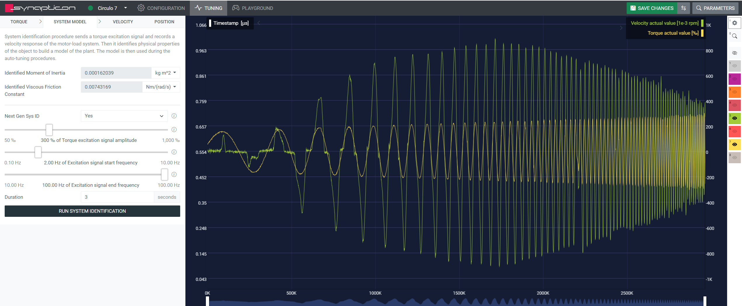
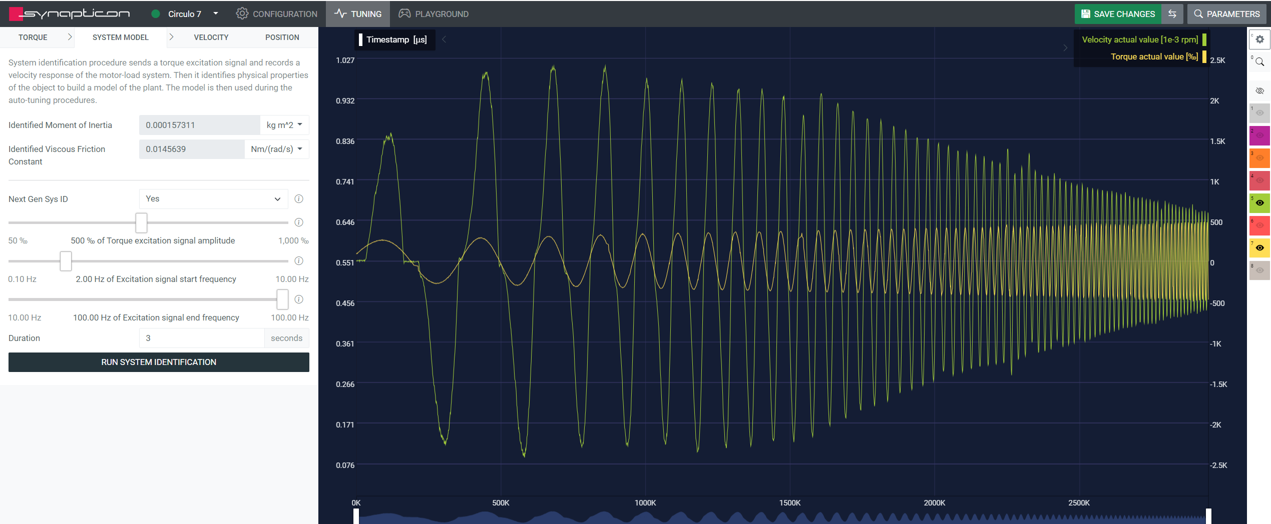
Torque excitation signal amplitude
This slider specifies the maximum per mill of the motor's rated torque that will be applied during the identification process. The actual torque applied will ramp linearly from 50% to 100% of the specified slider value.
-
Adjust the slider from lower to higher values, ensuring the system moves sufficiently, but within a safe range and that vibrations remain acceptable.
-
Lower slider values result in smaller vibration amplitudes and less stress on the mechanical structure. However, a low signal-to-noise ratio can lead to an imprecise model.
-
Additionally, if significant static friction is present, the algorithm might overestimate the load inertia and the viscous friction constant. An example of a low amplitude signal's effect can be seen in the image below:
-
Higher slider values improve the signal-to-noise ratio and help overcome static friction if the system does not move with initial lower settings. Be aware, however, that this might cause greater movement and oscillations in the mechanical system.
Excitation signal start frequency
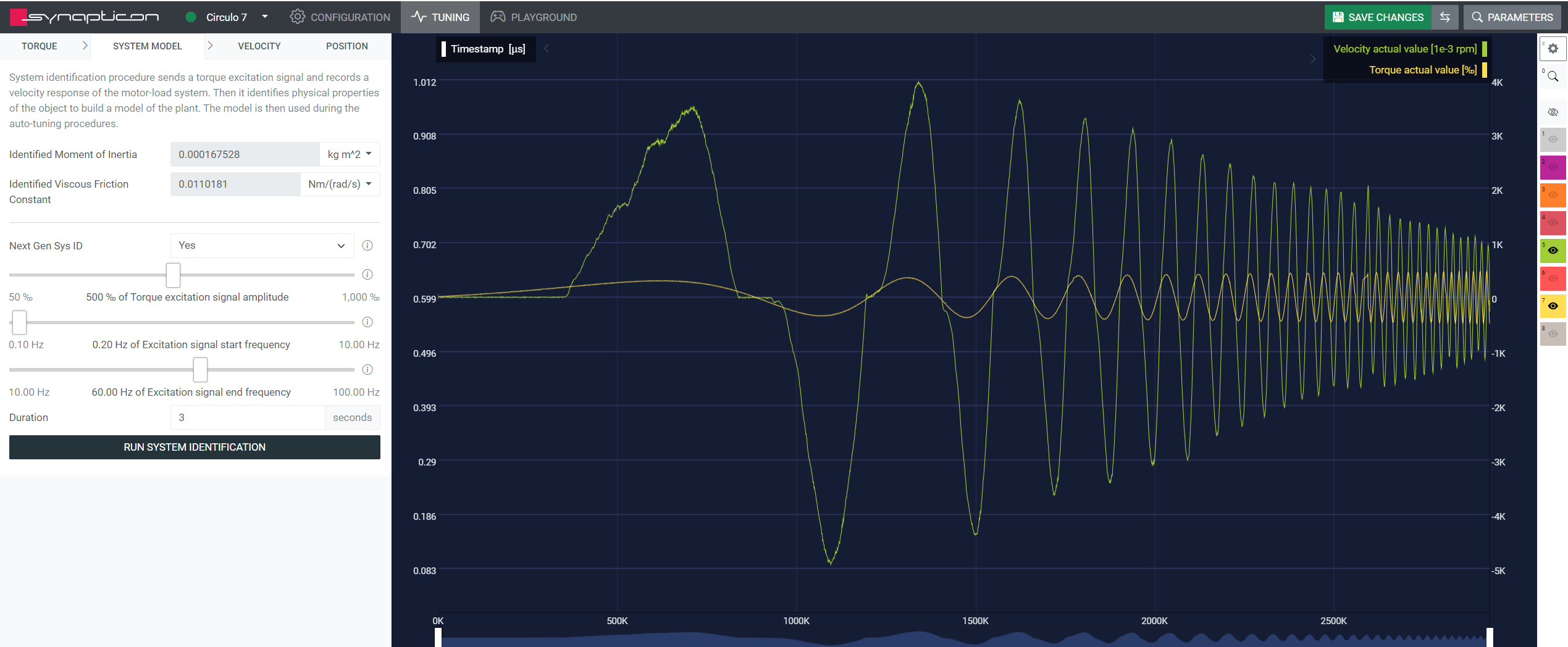
This defines the start frequency of the injected test signal.
-
Lower slider values result in longer periods of applied torque and thus help to overcome static friction.
-
At the same time, the overall motion range will increase substantially.
-
Additionally, model accuracy at lower frequencies will be increased.
-
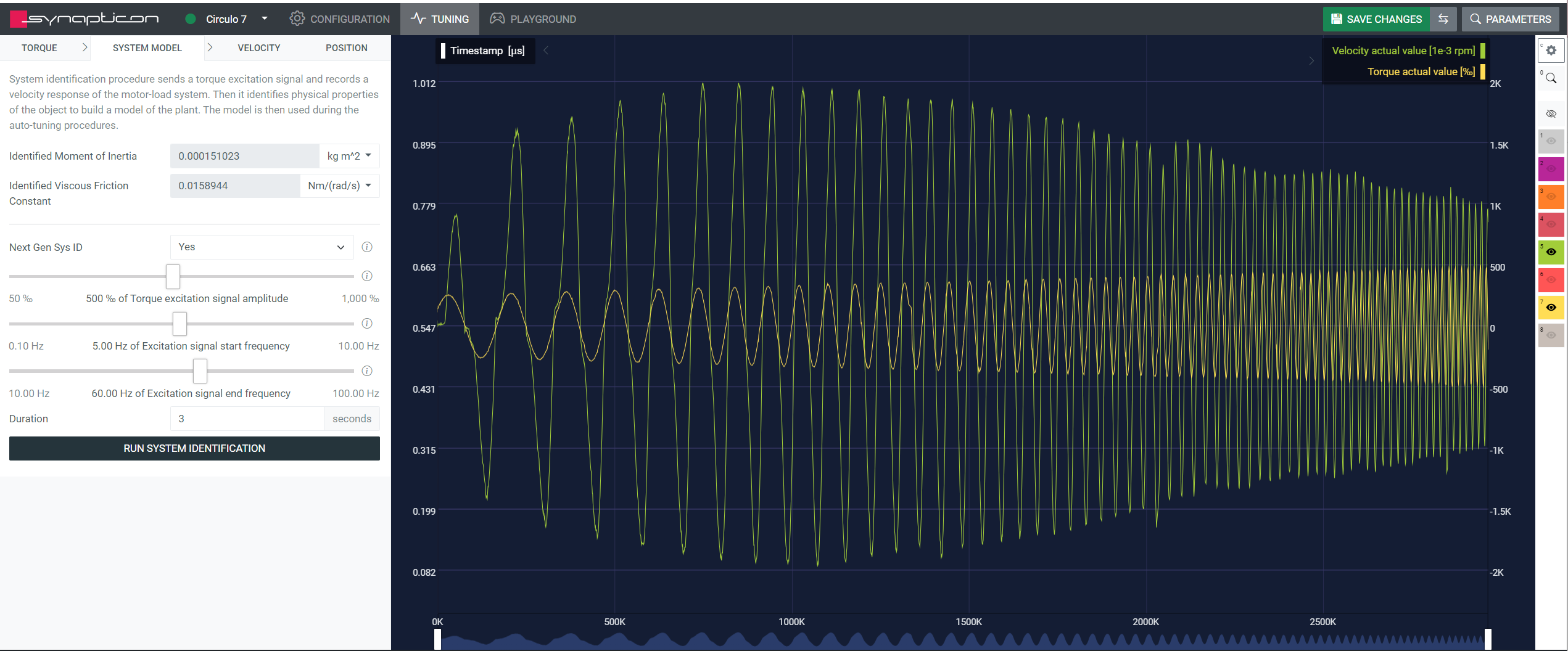
Higher slider values function poorly for systems with static friction.
-
The overall motion range will be significantly reduced.
-
The data will have more focus on the medium frequency range for the model identification, yielding higher accuracy there.
Excitation signal end frequency
This defines the end frequency of the injected test signal.
-
Lower slider values will exclude higher frequencies from the test signal, thus reducing model accuracy in this frequency range.
-
However, it can be beneficial to capture middle range frequency response more in detail.
-
The data will have more focus on the medium frequency range for the model identification, yielding higher accuracy there.
Duration
This is the time duration of the applied test signal.
-
Low values will result in a shorter identification procedure and thus less recorded data. Model accuracy will be decreased.
-
On the other side, resulting motion and mechanical stress will be reduced.
-
High values will result in more data and higher accuracy.
-
Motion range and mechanical stress will be higher.
After the System Identification was successfully executed, a set of default controller gains is calculated for position and velocity control loops.
Note: If the electromechanical system was changed, the identification should be repeated.
With the identified plant model, motion control loops can be designed with the auto-tuning functionality:
-
Position Autotuning for position control modes.
-
Velocity Autotuning for velocity control modes.
F.A.Q. (Frequently Asked Questions)
Do I have to repeat system identification after attaching a load to the system?
-
It is recommended to repeat the procedure.
What if my encoder has low resolution?
-
The velocity signal used in system identification will be more quantized, which may result in a less accurate model.
The system experiences overcurrent, overvoltage, or undervoltage during the system identification.
-
Check the motor and encoder configuration parameters.
-
Configure Max torque and Max current parameters according to the component with the lowest peak value in the system (motor, servo drive, gear).
-
Ensure the torque controller is functioning correctly.
-
Lower the torque excitation signal amplitude.
The power supply/servo drive shuts down during the procedure.
-
Most likely, the DC voltage increased due to the spinning motor, and the power supply safety mechanism activated.
-
Reduce the torque excitation signal amplitude or increase the excitation signal start frequency.
-
Configure or replace the power supply.
-
Use a Breaking Chopper.
Velocity amplitude is insufficient.
Increase the Torque excitation signal amplitude or reduce the Excitation signal start frequency.
Polarity of position and velocity encoders does not match. Check position encoder polarity.
-
This error is reported by the initial data consistency check. It is assumed that the derivative of position and velocity have the same sign.
-
Change the polarity of the encoder used for position feedback.
-
Alternatively, this can be caused by backlash or slipping of the mechanical components.
-
In some mechanical configurations, increasing the torque excitation signal amplitude or reducing the excitation signal start frequency can help.
Recorded data quality is critically low, cannot compute a model.
-
The error is reported during processing of the recorded data and can be caused by:
-
a highly nonlinear system,
-
high noise/quantization in the velocity signal, or
-
insufficient motion.
-
-
A typical solution would be to increase the motion range using the configuration sliders.
A linear model cannot be fit to the recorded data.
-
Linear model fitting error. This can be caused by a highly nonlinear system or by focusing the excitation frequency range on a nonlinear response.
-
A typical solution would be to increase the motion range and tweak the excitation frequency range using the configuration sliders.
Limited-Range System Identification Feature
The limited-range system identification feature allows the user to perform the system identification procedure while respecting user-defined position limits, even under the influence of gravity.
This feature is used in situations where loads are prone to fall without velocity or position control. Typical examples are unbalanced loads and robot links. Additionally, this feature can be used when system identification must be performed while strict position limits must be respected. When the above indicators are not met, the standard system identification procedure should be used.
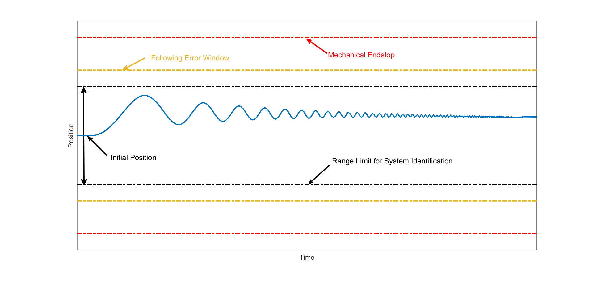
When enabling this feature, the permissible motion range must be specified via the Range Limit parameter. This parameter defines the permissible motion window around the initial position when the system identification process is started. The value is specified in position units, and applies symmetrically in both directions; therefore, the total window width is twice the defined range limit.
Note: Motion range limits that are too restrictive lead to aggressive control action in order to keep the load within the specified limits. As a general rule, start with low excitation signal amplitudes and increase gradually. Typically, the limited-range system identification requires significantly lower excitation amplitudes than the standard system identification procedure. Additionally, do not set the range limits stricter than necessary.
This feature relies on correct specification of the motor parameters - most importantly - nominal and maximum motor torque and tuning of the torque controller.
As an additional safety measure, it is recommended to configure the Objects Following error window (0x6065), Following error time out (0x6066), and Quick stop deceleration (0x6085) such that the system can be safely brought to a standstill in case the permissible motion range is violated during system identification. This can occur when the torque required to keep the system inside the limits cannot be delivered by the motor. In this case, try to reduce the excitation amplitude and increase the range limit.
The image below displays a typical configuration example.
Further Insights
When limited-range system identification is active, think of the motor torque as mimicking a spring. The spring gets stiffer as a range limit comes closer. Refer to the image below.
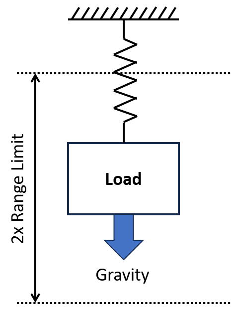
The virtual spring attached to the motor load creates a resonant system. The torque chirp excites this system for a short time at its resonance frequency, which leads to big movements. Thus, the chirp excitation amplitude should at first be set to its minimum, and then gradually increased.
To prevent aggressive control action, the value of the range limit should not be set smaller than necessary.
If loads are under the influence of gravity, the range limit should also not be set too high, because then, the load can gather significant momentum after opening the brake and can only be stopped with high motor torques.