Design Guide
This guide includes information to assist users in the design of parts used with the SOMANET Integrated Brake System.
Important:The torque limiter (notched wheel, friction elements and wave spring) must be designed and built by the end user.
Selecting Torque
Before the torque limiter can be attached onto an actuator or motor, it is important to select the braking torque. It must be set so that all components can withstand the instantaneous torque that occurs with a crash. It is also important to consider the components attached to the motor’s output shaft, for example, gearbox, torque sensor, etc., and the maximum torque that each can withstand.
How to Design the Parts to Reach a Defined Torque
Two methods can be used when designing parts to reach a defined torque:
-
Method 1. Purchasing torque limiter parts from Synapticon, or
-
Method 2. Designing and sourcing your own parts.
Each method is described in the sections that follow.
Method 1. Purchasing torque limiter parts from Synapticon
When purchasing torque limiter parts from Synapticon, it is important to understand how to set the torque. This section explains how this can be done.
The torque limiter is composed of the notched wheel, two friction elements and a spring.

Figure 1 - Torque limiter mechanical composition
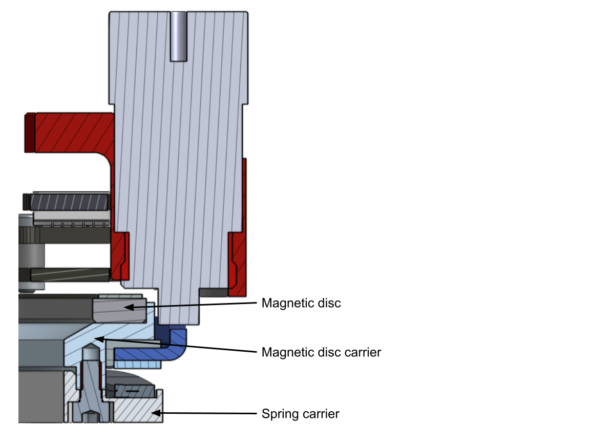
Figure 2 - Torque limiter, solenoid actuator, and Circulo - cut view

Figure 3 - De-energized and energized solenoid actuator with Circulo, shaft elements and the integrated brake system
Spring chamber - Setting the slipping torque of the torque limiter
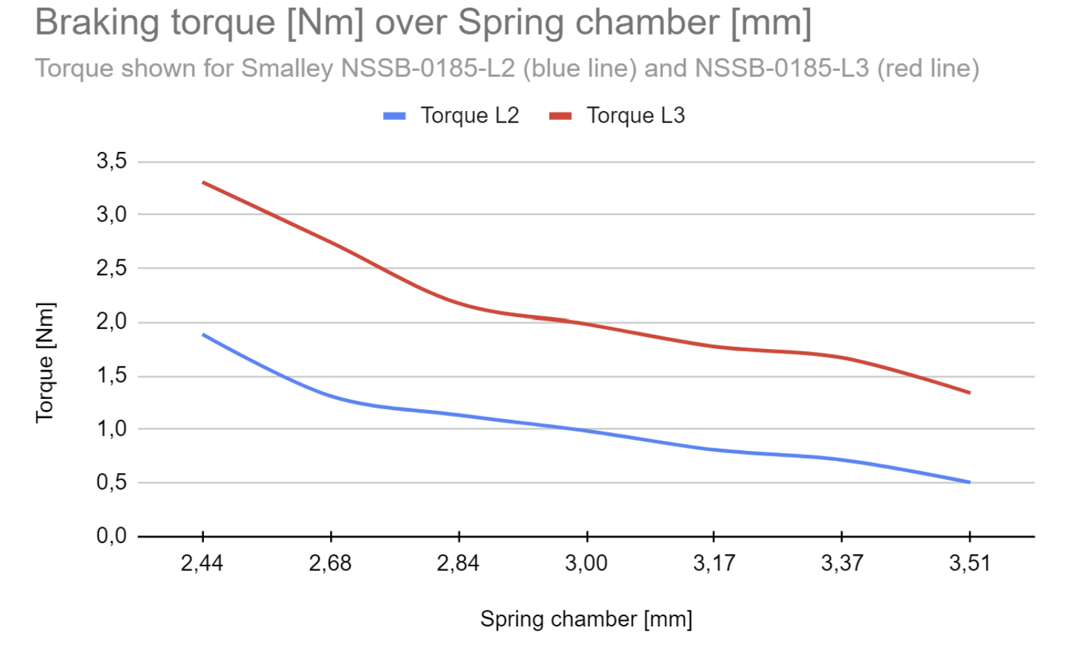
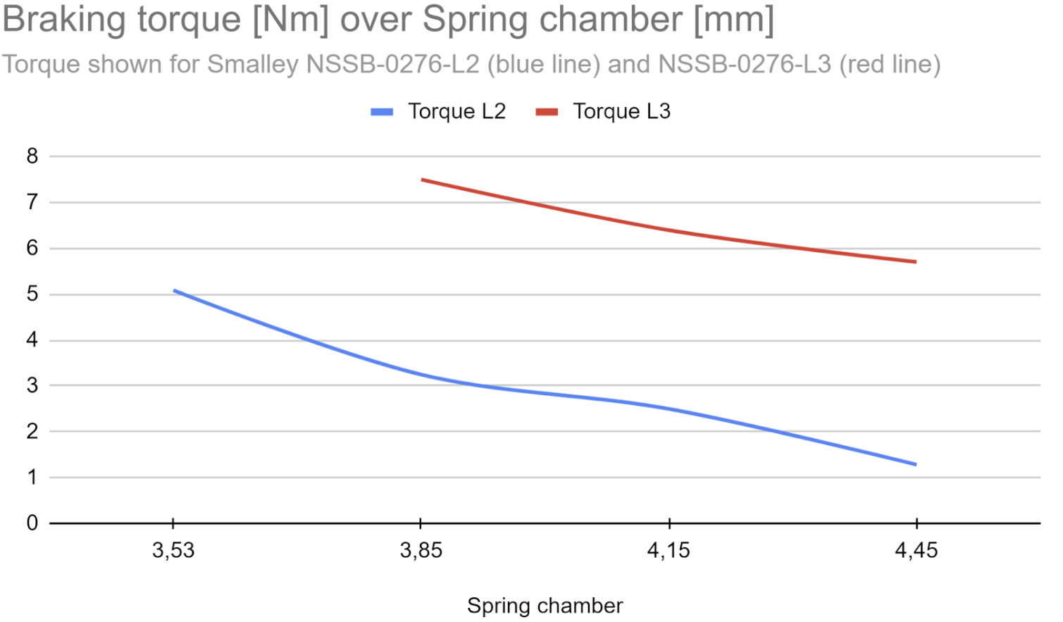
The spring chamber describes the working height of the spring. The more the spring is compressed, the more torque will be set in the torque limiter.
In the braking torque over the spring chamber diagrams, the resulting torque is displayed for each one of the four springs for the corresponding spring chamber (refer to the diagrams below).
The height of the spring chamber is set by constructive measures, more specifically by the height between the spring carrier and the magnet carrier.
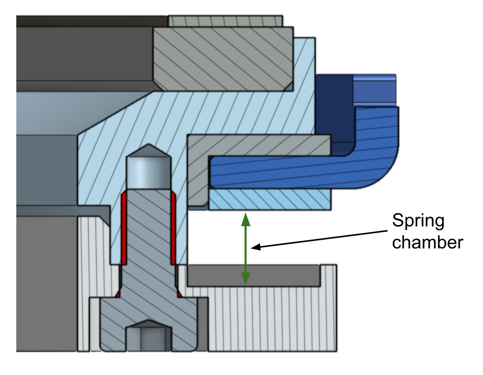
Figure 4 - Representation of the spring chamber set by constructive measures
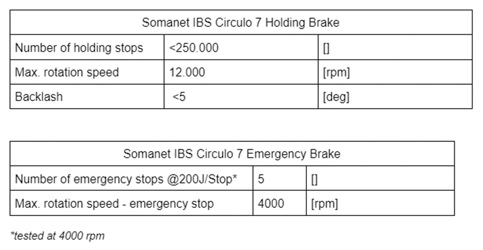
Torque Limiter Technical Specifications
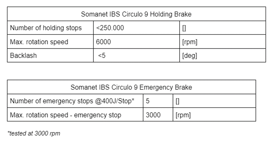
Circulo 7
Circulo 9
Method 2. Designing and sourcing your own parts
Torque Limiter Sizing
Once the desired braking torque is established, the brake system components must be sized accordingly. The following parts define and influence this torque:
-
friction disc, radial friction element,
-
bearing, radial-axial friction element, and
-
wave spring.
Each of these is explained in the text that follows.
The formula for the braking torque is:
 (Formula 1)
where:
Mb = Braking torque [Nm]
μ= Coefficient of friction [ ]
Fs = Spring force [N]
r = Nominal radius of the friction elements [m]

Figure 5 - Nominal radius
As friction is an organic process, the braking torque is rarely precisely reproducible; it depends on the surfaces, tolerances, materials, etc.
The spring loads are also affected by a certain tolerance. (For additional information, refer to the section Wave Spring that follows.) Therefore, it is important to work with a safety factor. In order to not exceed the maximum allowed torque, the desired torque must be multiplied by the safety factor: Fs = spring force [N].
Friction Disc, Radial Friction Element
The material used in the friction disc’s composition must be selected to match the allowed braking torque. There are many materials that can be used, including metal and plastics over composite materials, which are built to have a high friction coefficient.
The selected material should have a good ratio between stiction and friction. The closer the breakaway torque is to the braking torque, the gentler the breakaway will be for the system. Therefore, it is recommended to use Polyoxymethylene (POM) - also known as acetal. It is a durable material with good thermal resistance and acceptable friction/stiction coefficients.
If the system requires a higher friction coefficient, explicit friction materials can also be used.
Note: As the torque limiter is located close to the drive, it is not recommended to use metal friction elements, as they might produce metal dust while slipping and create a short circuit.
Bearing, Radial-Axial Friction Element
The bearing separates the notched wheel from other metal parts. Without this part, the aluminum/metal connection causes galling.
The material used in the bearing’s composition must fulfill the same requirements as the material used in the friction disc’s composition. Therefore, it is recommended to use Polyoxymethylene (POM), also known as acetal.
Note: Because the friction materials mentioned above are soft, they will not work when a crash occurs, as there is a high radial force on the shaft extension and the notched wheel.
Wave Spring
Nested wave springs can produce an extremely high force in limited space. This force is used to increase the braking torque (refer to Formula 1).
As a result, when defining the actual torque, the following must be considered:
-
spring load tolerances, and
-
how the spring is centered.
Centering the Wave Spring
The wave spring must be centered well, as insufficient centering can cause an imbalance - and thus vibrations - while operating at high speeds. The wave springs can be centered by their inner or outer diameter, which differ in loaded or unloaded state. Refer to your manufacturer’s mounting instructions for additional information.
Note: For an easier assembly process, the motor shaft extension should be centered with the motor shaft before the spring is contracted. By doing so, all parts can be loosely pre-assembled and the screws can be tightened, which will compress the spring to its final position (working height).
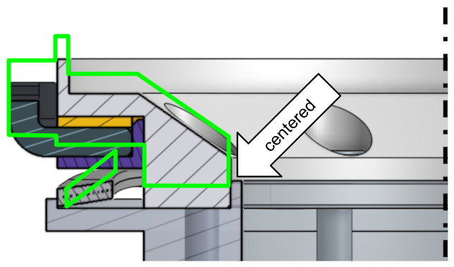
Figure 6 - Centering the wave spring
Supplemental torque limiter reference design information
Select the appropriate link below to download the CAD file desired.