Regenerative Energy
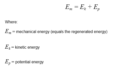
An electric motor can also work as a generator when gravity or deceleration drives it in generator mode. In this case, power is returned into the power line. The amount of regenerated energy depends on the mechanical energy. Higher deceleration and higher inertia produce more regenerated power. However, this regenerated energy can cause overvoltage on the DC link, which is dangerous for all equipment on the same power bus. It is important to prevent overvoltage so that the system works properly. The regenerated energy can either be stored in a battery, e.g., in an AGV, or burned by resistors (through a braking chopper or shunt).
Estimation of Regenerated Energy
Regenerated energy comes from mechanical energy. The load, gravity, and deceleration are important factors in determining how much energy is regenerated:
To estimate the DC bus capacitor and braking resistor:
-
Calculate the regenerated energy.
-
Calculate the maximum capacitor value using the overvoltage protection level.
-
Calculate how much energy will be dissipated.
-
Calculate how much power must be dissipated by the braking chopper and the safe deceleration cycle performance.
Managing Regenerated Power in DC Bus Systems
In many applications, machines can feed energy back into the DC bus during deceleration. Properly restoring or dissipating this regenerated power is critical for system safety and efficiency.
Restoring The Regenerated Energy (Energy Recovery)
If the system uses batteries or large capacitors as a power supply, the regenerated energy can be stored and reused. This method is energy-efficient and can reduce long-term operational costs. However, depending on the application. the initial cost of components, i.e., batteries or high-capacity capacitors, may outweigh the benefits.
Dissipating Regenerated Power (Overvoltage Protection)
In systems without energy storage, it is essential to protect the DC bus from overvoltage by dissipating excess energy through braking resistors. Typically, this occurs using a braking chopper, which activates when the DC voltage exceeds a threshold.
DC Bus Capacitance Role
In ideal cases, if the DC bus capacitance is large enough, it can absorb the regenerated energy during braking. When this is sufficient, a braking resistor or chopper is not required. However, in most dynamic applications, capacitors alone are not enough and active dissipation is required to avoid overvoltage faults.
Braking Chopper
A braking chopper (or other shunt circuit) is used to burn energy that cannot be recuperated. It is recommended to use SOMANET drives together with one (or more) SOMANET Braking Chopper 48V 500W.
The number of braking choppers depends on the amount of excessive energy (for peak power) and the frequency of regeneration (thermal load).
Protection Features and Limitations
The SOMANET Braking Chopper includes built-in protection mechanisms:
-
Overvoltage Protection
-
Overcurrent Protection
-
Over Temperature Protection
If the chopper becomes overloaded, it will automatically shut down to protect itself.
Attention: When the braking chopper shuts down due to an overload, the DC bus voltage may rise uncontrollably.This will trigger an overvoltage fault in the drive, potentially disabling the safe deceleration of the robot.
Virtual Braking Chopper
Overview
When a motor enters regeneration mode, it increases the voltage on the DC link. Virtual Braking Chopper can be used to dissipate this excess energy. Once configured, Virtual Braking Chopper monitors the voltage on the drive. If the voltage exceeds the set threshold, it begins to inefficiently inject current into the motor, thereby burning off the excess energy generated.
Uses for Virtual Braking Chopper
Since this feature inefficiently injects current into the motor, it causes the motor to heat up. Therefore, Virtual Braking Chopper is ideally suited for applications where the motor does not frequently enter regeneration mode.
Note: Users should thoroughly test this feature to ensure that it meets their specific requirements.
The injection of d-axis current into the motor can potentially generate unwanted torque in certain scenarios. This may occur when the commutation offset is not precisely calibrated or when dealing with interior permanent magnet motors. To mitigate these issues, it is recommended to implement this feature in conjunction with a velocity controller or position controller, either integrated into the drive system or managed by a master control unit.
Note: Users should thoroughly test this feature to ensure that it meets their specific requirements.
Configuring Virtual Braking Chopper
Follow the steps below to enable and configure Virtual Braking Chopper on the drive.
Enable the Feature
-
Access the "Virtual Braking Chopper Enabled (0x2010:13)" object on the drive.
-
Set this object to enable the Virtual Braking Chopper feature.
Configure the Voltage Threshold
-
Use the "Virtual Braking Chopper Voltage Level (0x2010:15)" object to set the voltage threshold.
-
Set the threshold higher than the normal operating voltage to prevent unnecessary activation.
Example:
Normal operating voltage: 48000 mV
Recommended threshold: 49000 mV or higher
Adjust the Current Injection Rate
-
Control the rate of the current injection using the "Virtual Braking Chopper Gain (0x2010:14)" object.
-
Fine-tune this value based on your specific requirements.
Set the Notification Level
-
Configure the notification level according to your preferences:
-
Error notification (e.g., overvoltage error)
-
Warning notification (default setting)
-
No notification
-
Ensure that the voltage threshold is appropriately higher than the normal operating voltage to prevent unnecessary activation during regular operation.
Important:Virtual Braking Chopper injects current in the d-axis direction, which could potentially generate torque in certain scenarios, such as: Inaccurate commutation offset, Use with interior permanent magnet motors. For optimal performance, consider implementing this feature alongside a velocity controller or position controller, either on the drive or master control system.